
When electrical current needs a safe path to earth, a Ground Bus Bar provides a central connection point. Usually made from copper or tinned copper, it sits inside a panel, switchboard, or grounding enclosure. Short, properly sized conductors connect equipment grounding wires to this bar. That arrangement makes grounding paths easier to inspect, test, and maintain.
A Ground Bus Bar helps bond metal enclosures, cable trays, service equipment, and other conductive parts. During a fault, it can help carry unwanted current toward the grounding system, supporting protective devices such as breakers. It also reduces confusion by gathering connections in one visible location. However, it does not replace system design, bonding rules, or qualified inspection. The exact setup depends on local electrical codes, system type, and manufacturer instructions.
In practical work, details matter. A loose lug, painted mounting surface, or undersized conductor can weaken the connection. Technicians often check torque, continuity, corrosion, and labels before energizing equipment. Not every bar is interchangeable. Some installations require isolated neutral and ground bars; others do not. This distinction is easy to overlook. I should be careful here: a bus bar may look simple, but its safety depends on the entire grounding and bonding network. This guide explores its purpose, common applications, selection factors, and installation considerations through established electrical practice and verified product information. When uncertainty remains, a licensed electrician should review the design.
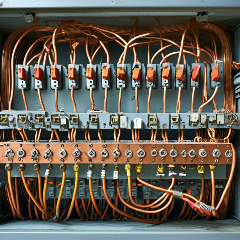
A ground bus bar is a conductive metal strip used to collect and distribute grounding connections. It is usually installed inside an electrical panel, service enclosure, or equipment cabinet. Individual grounding wires attach to the bar through labeled screw terminals. The bar then connects to the grounding electrode system or another approved grounding point.
Its purpose is practical and protective. During a fault, unwanted electrical current needs a low-resistance path back to the source. A properly connected ground bus bar helps protective devices respond quickly. It also keeps several grounding conductors organized, visible, and easier to inspect. In a workshop panel, for example, green or bare copper wires may enter from lighting circuits, receptacles, and metal equipment. Each wire should have a secure termination, with no loose strands beneath the clamp.
Details matter here. The bar must match the enclosure, conductor size, and applicable electrical rules. In some panels, grounding and neutral conductors must remain separated. In service equipment, their arrangement can differ. This is where casual assumptions become dangerous. I have seen installations that looked tidy but had an incorrect bonding connection. Appearance alone proves little. A qualified electrician should verify continuity, torque, bonding, and local code requirements with suitable testing equipment. Even a small labeling error can make later maintenance slower and less reliable. A ground bus bar is simple hardware, but its safety function depends on the entire grounding system.
A ground bus bar is a conductive metal strip that gathers protective grounding conductors in an electrical panel. It creates a common connection between circuit grounds, the panel enclosure, and the grounding system. When equipment insulation fails, fault current travels through this low-resistance path. The current can then trigger a protective device and disconnect power quickly. The path stays short. A secure connection is essential.
The bus bar does not normally carry operating current. It carries fault current when a problem occurs. Each grounding conductor is fastened to a separate terminal, while the bar bonds electrically to the enclosure. In some panels, neutral and ground connections must remain separated. That distinction matters because an incorrect bond can place normal current on metal parts. A qualified installer checks the electrical design, conductor size, terminal capacity, and local requirements before energizing the panel. Tightening matters too, although over-tightening may damage a terminal. Corrosion, loose strands, and crowded terminals can weaken the connection over time. A visual inspection alone may miss these issues. Testing continuity and checking for unwanted voltage between grounded parts provides better evidence. One point deserves reflection: a tidy bus bar is not automatically a safe one. Its reliability depends on correct bonding, suitable materials, careful installation, and periodic inspection.
A ground bus bar is a conductive strip that gathers grounding and bonding conductors in an electrical panel. It creates a low-resistance path for fault current. This path helps protective devices operate quickly during abnormal conditions.
Copper is common because it conducts well and handles repeated thermal stress. Aluminum may reduce weight and cost, but it needs careful connection design. Many bus bars use tin plating to slow oxidation and improve terminal contact. The bar usually includes drilled holes, threaded points, or clamp-style terminals. These details control how firmly each conductor is secured. Insulating supports keep the bar separated from the enclosure when required. Mounting brackets also need enough mechanical strength for large cables. Small parts matter.
In panel inspections, I check for loose screws, damaged threads, corrosion, and crowded terminals. A clean appearance does not prove a reliable connection. The conductor size must match the expected fault current and installation rules. Bonding jumpers may connect the bar to doors, cable glands, or metal enclosures. Some designs fail because the bar is placed where tools cannot reach it. Others leave too little space for future circuits. That is easy to overlook. Material selection also requires reflection. Copper may be excellent electrically, yet poor spacing or incorrect torque can still create heat, arcing, and unsafe touch voltage. Each installation deserves verification with approved drawings, torque requirements, and qualified testing.
What Is a Ground Bus Bar and What Is It Used For?
A ground bus bar is a conductive metal strip that gathers grounding conductors in one organized location. It helps route fault current safely toward the grounding system, allowing protective devices to operate quickly. In a residential service panel, bare or green wires from branch circuits commonly terminate on this bar. The bar is also bonded to the enclosure, so exposed metal parts do not remain energized during a fault. The difference matters.
Ground bus bars appear in commercial switchboards, distribution panels, and industrial control cabinets. In a control cabinet, they connect the enclosure, cable shields, motor frames, and equipment grounding conductors. In data rooms, they support bonding between racks and the building grounding network. Renewable power equipment may use them to bond metal frames, inverters, and protective devices. Connections must stay visible.
Installation quality affects performance. Conductors should match the required size, use suitable terminals, and remain firmly tightened according to documented procedures. A loose connection can create heat, corrosion, or unreliable fault clearing. The ground bar must not be confused with the neutral bar, especially in downstream panels where separation is normally required. Local electrical codes and equipment instructions determine the exact arrangement. A common field mistake is adding too many wires under one terminal. That saves space briefly, but it can weaken contact and complicate inspection. Periodic checks should look for discoloration, damaged insulation, loose hardware, and accidental neutral-to-ground contact.
| Common Application | Primary Purpose | Typical Installation Location | Conductors Connected | Key Design Considerations | Safety and Compliance Notes |
|---|---|---|---|---|---|
| Main Electrical Service Panel | Provides a common point for terminating equipment grounding conductors and, where permitted, bonding the service enclosure to the grounding electrode system. | Main service equipment or service-rated switchboard. | Grounding electrode conductor, equipment grounding conductors, bonding jumpers, and grounding conductors from feeder circuits. | Must be properly bonded to the service enclosure and sized for the grounding and bonding requirements of the installation. | Neutral-to-ground bonding is generally permitted at the service disconnecting means, but not downstream in separately supplied panelboards unless specifically allowed by the applicable electrical code. |
| Subpanels and Distribution Boards | Collects equipment grounding conductors and maintains a continuous fault-current path back to the source. | Panelboards supplied by a feeder or transformer secondary. | Feeder equipment grounding conductor, branch-circuit grounding conductors, and bonding conductors. | The ground bus should be electrically isolated from the insulated neutral bus in typical downstream panelboards. | Enclosures, raceways, and metallic parts must be bonded according to the applicable electrical installation rules. |
| Industrial Control Panels | Connects the panel enclosure, backplate, cable shields where required, and equipment grounding conductors to a common grounding point. | Motor-control centers, automation cabinets, and machine control enclosures. | Control-circuit grounding conductors, protective bonding conductors, enclosure bonding jumpers, and selected shield drains. | Keep protective bonding connections reliable and separate sensitive signal-ground practices from protective earth requirements unless the design specifically combines them. | Grounding arrangements should follow the equipment design, the installation code, and the control-system manufacturer’s approved wiring method. |
| Data and Telecommunications Rooms | Provides a centralized bonding point for racks, cabinets, cable trays, and telecommunications bonding conductors. | Telecommunications entrance facilities, equipment rooms, and network rooms. | Rack bonding conductors, metallic tray bonds, telecommunications bonding conductors, and bonding connections to building steel where applicable. | Use short, direct bonding paths and avoid relying on rack mounting hardware alone for bonding continuity. | Bonding infrastructure helps reduce potential differences and supports effective fault and surge-current paths; it is not a substitute for proper signal-cable design. |
| Commercial Building Electrical Rooms | Creates an organized termination point for grounding and bonding conductors serving building electrical equipment. | Electrical rooms, mechanical rooms, and main distribution areas. | Grounding electrode conductors, bonding jumpers, feeder grounding conductors, and bonds to structural or mechanical systems where required. | Provide adequate space, accessible connections, clear identification, and protection from mechanical damage or corrosion. | Grounding and bonding conductors must be continuous or connected with approved methods suitable for the conductor material and environment. |
| Generator and Transfer Equipment | Establishes grounding and bonding connections for the generator frame, transfer equipment, and associated circuits. | Generator rooms, outdoor generator enclosures, and automatic transfer equipment sections. | Generator equipment grounding conductors, frame-bonding conductors, grounding electrode conductors, and system bonding jumpers where applicable. | The system bonding arrangement depends on whether the generator is a separately derived system and on the transfer-switch configuration. | Improper neutral-to-ground bonding can create parallel neutral-current paths; the grounding design must match the system configuration and local code requirements. |
| Solar Photovoltaic Systems | Bonds photovoltaic equipment and exposed conductive parts to the equipment grounding system. | Combiner boxes, inverter equipment, disconnect enclosures, and photovoltaic equipment areas. | Module and array equipment grounding conductors, inverter grounding conductors, metallic support structure bonds, and enclosure bonding conductors. | Connections must be suitable for outdoor exposure, ultraviolet radiation, temperature changes, and the materials used in the mounting system. | Follow the applicable photovoltaic electrical requirements and use listed bonding hardware or methods compatible with the equipment and environment. |
| Motor and Drive Systems | Provides a low-impedance protective bonding path for motors, variable-frequency drives, disconnects, and motor enclosures. | Motor-control panels, drive cabinets, starter enclosures, and equipment skids. | Motor circuit equipment grounding conductors, enclosure bonds, cable armor or metallic raceway bonds, and drive-panel grounding conductors. | Use a grounding path capable of carrying fault current and consider high-frequency bonding practices for drive-generated electrical noise. | Grounding does not replace overload, short-circuit, or overcurrent protection; all protective functions must be designed separately. |
| Lightning and Surge Protection Systems | Provides a designated connection point for bonding surge protective devices and related grounding conductors. | Service entrances, distribution equipment, communications entrances, and surge-protection assemblies. | Surge protective device grounding conductors, bonding conductors, and connections to the grounding electrode system. | Keep conductors as short and straight as practical to reduce impedance during transient events. | A ground bus bar supports bonding but does not eliminate the need for correctly designed surge protection, grounding electrodes, and conductor routing. |
| Renewable Energy and Battery Systems | Connects exposed conductive parts and equipment enclosures to the protective grounding system. | Battery cabinets, energy-storage enclosures, inverter rooms, and renewable-energy equipment rooms. | Battery enclosure bonds, inverter grounding conductors, equipment grounding conductors, and grounding electrode conductors where required. | Select materials and connection methods that tolerate the system voltage, fault-current level, temperature, moisture, and possible corrosive conditions. | Grounding and bonding must be coordinated with battery-system protection, insulation monitoring, disconnecting means, and the applicable electrical code. |
A ground bus bar provides a shared connection point for equipment grounding conductors. It helps fault current travel safely back to the source, allowing protective devices to respond quickly. Selection should begin with the enclosure, circuit count, and conductor sizes. Choose a bar with enough terminals, suitable ampacity, and corrosion-resistant construction. Check whether the mounting hardware supports bonding to the enclosure. A bar that physically fits may still be electrically unsuitable.
Installation requires careful preparation.
De-energize the equipment and verify the absence of voltage with a properly rated tester. Mount the bar firmly on a clean, conductive surface, unless an insulated design is required. Route grounding conductors neatly, avoid sharp bends, and strip only the required insulation. Tighten each terminal to the specified torque. Loose connections can create heat and unreliable fault paths. Do not place multiple conductors under one terminal unless that terminal is specifically rated for it. In a subpanel, keep neutral conductors isolated from the ground bar according to local electrical rules.
Tips:
Label each conductor before moving it. Leave space for future circuits. Photograph the original layout. During inspections, I have seen crowded bars hide loose strands and incorrect terminations. I once underestimated how quickly a small enclosure becomes difficult to service. Recheck conductor sizing, bonding points, and torque values before closing the cover. Local code requirements can differ, so a qualified electrician should review uncertain installations.