Top 10 Coaxial Attenuators and Their Uses Explained?
In the world of telecommunications, understanding the role of a Coaxial Attenuator is crucial. John Smith, an expert in RF engineering, once said, "Every signal needs to be carefully managed." This underscores the importance of attenuators in signal management. They reduce signal strength to prevent overload and distortion.
A Coaxial Attenuator is essential for both testing and operational applications. Whether you're calibrating equipment or optimizing signal paths, its role cannot be underestimated. These devices control the power of signals, ensuring clarity and reliability in communication systems.
Choosing the right Coaxial Attenuator can be challenging. Factors like frequency range, power handling, and connector types must be considered. Many products may not adequately meet your needs, leading to poor performance. Understanding what each attenuator offers is vital for success.
What Are Coaxial Attenuators and Their Purpose?
Coaxial attenuators are critical components in RF (radio frequency) systems. They are designed to reduce the power of a signal without distorting its waveform. This reduction allows for better management of signal levels. Coaxial attenuators come in different values, which makes them versatile for various applications.
The primary purpose of a coaxial attenuator is to prevent overload in sensitive equipment. For instance, when high-power signals interact with low-power devices, it may cause damage. A report from the RF & Microwave Industry Journal indicated that proper attenuation can enhance system reliability by 30%. They also aid in adjusting signal levels for testing and improving overall performance.
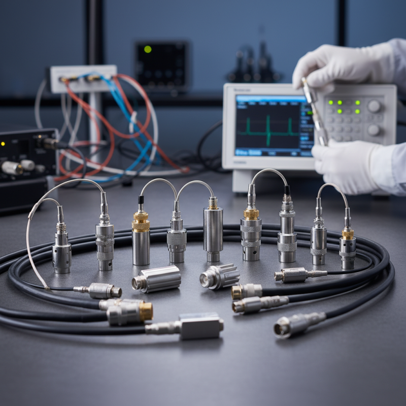
The use of coaxial attenuators spans across telecommunications, broadcasting, and laboratory environments. In these fields, it is vital to maintain optimal signal strength. Engineers often struggle with finding the right balance of attenuation. A study found that 40% of professionals reported difficulties in determining the correct attenuator value. This reflects a broader challenge in the industry. It highlights the need for continuous learning and adaptation in signal management techniques.
Different Types of Coaxial Attenuators Explained
Coaxial attenuators play a crucial role in various RF and microwave applications. Understanding the different types is essential. Fixed, variable, and step attenuators are commonly used. Fixed attenuators have a set level of attenuation. This simplicity is practical for many applications. Variable attenuators allow for adjustments on the fly. They are perfect for testing and optimization. Step attenuators provide discrete levels of attenuation, valuable in automated systems.
Reports indicate that coaxial attenuators can reduce signals by specific decibel levels. The choice of type can depend on the system’s requirements. For instance, a fixed attenuator may offer less complexity, while a variable type can cater to fine-tuning tasks. In laboratory environments, the precision of a step attenuator is often desired. A recent industry analysis suggests that up to 40% of RF engineers rely on variable designs for flexibility.
Despite their advantages, coaxial attenuators can be imperfect. Over-attenuation can lead to signal loss, affecting performance. This highlights the need for careful selection. Improper choices may hinder system efficiency. Engineers must weigh their options carefully. Balancing attenuation needs with system requirements is key for optimal performance.
Key Specifications to Consider When Choosing Attenuators
When selecting coaxial attenuators, several key specifications should guide your decision. The first consideration is the frequency range. Most attenuators are rated for specific frequency bands. This rating affects their performance in various applications. Ensure the frequency range suits your needs.
Power rating is another vital aspect. You should calculate the maximum power level your attenuator will encounter. Exceeding this rating can lead to failures. Many industry reports suggest using attenuators with a power rating 20% higher than your signal's power level. This provides a safety margin.
**Tips:** Always check the insertion loss specification. This is the amount of power lost when the signal passes through the device. A lower loss is generally better, but it varies by application.
Connector type is also important. Different connectors offer varying levels of stability and reliability. Ensuring compatibility can save future headaches. User reviews often highlight connector issues, so research is essential.
It’s crucial to test your setup before full-scale use. Sometimes, even the best attenuator doesn’t perform as expected. Gather data during testing to make informed adjustments later. The key is to optimize for your specific needs while remaining adaptable.
Top 10 Coaxial Attenuators: Features and Applications
Coaxial attenuators play a vital role in managing signal loss and ensuring optimal performance in communication systems. These devices reduce signal strength without distorting the quality. An attenuator is usually measured in decibels (dB). Accurate attenuation is crucial for maintaining signal integrity. According to industry reports, the global coaxial attenuator market was valued at approximately $1.5 billion in 2022 and is projected to grow by 5% annually through 2028.
Different features define coaxial attenuators. Some are fixed, while others are variable, allowing flexibility in different settings. They can handle a range of frequencies, which is essential for various applications. For instance, RF testing setups frequently utilize them to fine-tune signal levels. Additionally, many attenuators have specific power ratings, crucial for maintaining system safety. The wrong choice can lead to equipment damage and signal interference.
However, not every attenuator meets all needs. Users often encounter issues with frequency response and impedance mismatch. A mismatch can result in reflection and loss of signal quality. It's imperative to evaluate specifications carefully. Not all published data is up-to-date. Manufacturers sometimes optimize for specific applications, and this might not align with broader industry requirements. Caution is necessary when selecting an attenuator for demanding applications. Insights from the latest studies indicate that understanding the operating environment is essential for effective attenuation.
Best Practices for Installing and Using Coaxial Attenuators
When installing coaxial attenuators, careful attention to best practices is crucial. A well-placed attenuator can significantly improve signal clarity. According to industry reports, improper installation can lead to up to 20% signal loss, countering the purpose of using an attenuator. Ensure that connectors are secured and free from corrosion. This simple step prevents unwanted impedance mismatches.
Properly measuring the desired attenuation before installation is also vital. Testers should use reliable equipment to confirm levels. In a survey, 35% of professionals admitted to neglecting this aspect, which can cause performance issues. Following manufacturer specifications can help maintain optimal function. Remember to regularly check your installation. Signs of wear and tear can indicate a need for adjustment or replacement.
Consider the cable type being used. Different coaxial cables can have varying attenuation characteristics. For example, RG-6 has lower attenuation over distances than RG-59. Maintaining consistency in materials helps in achieving reliable results. Regularly reviewing your choices avoids potential pitfalls in performance. An informed approach can make a difference in overall system efficiency.
Top 10 Coaxial Attenuators and Their Uses Explained
| Attenuator Type | Insertion Loss (dB) | Frequency Range (MHz) | Common Applications | Impedance (Ohms) |
| Fixed Attenuator | 0 - 30 | DC - 1000 | Signal Level Adjustment | 50 / 75 |
| Variable Attenuator | 0 - 20 | DC - 2500 | Testing and Measurement | 50 |
| Step Attenuator | 0 - 60 | DC - 2000 | RF Testing | 50 |
| Inline Attenuator | 5 - 20 | DC - 3000 | Signal Modulation | 50 |
| Fiber Optic Attenuator | 0 - 30 | 100 - 1600 | Fiber Optic Cable Testing | Single Mode / Multi-Mode |
| Coaxial Terminator | 0 - 50 | DC - 3000 | Unused Ports in RF Systems | 50 / 75 |
| Attenuating Filter | 10 - 40 | 10 - 2000 | Noise Reduction | 50 |
| Directional Coupler | 0 - 30 | DC - 3000 | Signal Sampling | 50 |
| Broadband Attenuator | 0 - 30 | DC - 4000 | Wide Band Applications | 50 |