What Is Dot Peen Marking and How Does It Work?
Dot Peen Marking is a permanent identification method used on metal parts, tools, nameplates, and industrial equipment. A marking stylus strikes the surface repeatedly, creating a series of controlled dots. These dots form letters, numbers, logos, Data Matrix codes, or traceability records. The result resembles small punched impressions rather than ink.
According to Michael J. Stoll, an industrial marking specialist, “Marking quality begins with controlled contact, not maximum force.” This principle explains the process well. The machine must balance pin pressure, dot spacing, speed, and material hardness. Too little force creates faint characters. Too much force may deform thin stainless steel or weaken a delicate component. Small differences matter.
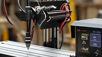
A typical system includes a marking head, carbide or diamond-tipped pin, controller, and software. The operator places the part into a fixture, enters the required code, and starts the cycle. The pin moves across the surface, striking precise locations. No stencil is required. No wet ink is involved.
Dot Peen Marking works especially well where durability and readable traceability are essential. It can withstand abrasion, heat, oil, and many industrial cleaning processes. Yet it is not perfect. Curved surfaces, uneven finishes, and poor fixturing can reduce readability. Even experienced technicians must test settings on sample parts. The best mark is not always the deepest one. It is the clearest, most consistent, and least damaging mark for that material.
Dot Peen Marking Defined: A Permanent Impact-Marking Process for Industrial Parts
Dot peen marking is a permanent impact-marking process for industrial parts. A hardened stylus repeatedly strikes the surface, creating a pattern of small, controlled indentations. These dots form letters, numbers, logos, serial codes, and machine-readable symbols. Unlike printed labels, the mark remains visible after handling, cleaning, and moderate surface wear.
The marking head moves across the component under programmed control. Each impact depends on force, spacing, speed, and stylus condition. On a steel gearbox housing, for example, the result may be a deep identification code near the mounting flange. On thinner sheet metal, excessive force can cause distortion. Material hardness and surface finish also affect contrast and readability. Practical testing is essential.
Dot peen systems suit traceability work because they need no ink, solvents, or separate labels. They can mark flat surfaces, curved areas, and some irregular components with suitable fixtures. However, the process is not perfect. Deep marks may weaken thin parts, while shallow marks can disappear under paint or corrosion. Dust, vibration, and poor alignment can reduce code quality. Operators should inspect sample marks, verify data, and review settings instead of trusting automation blindly. A readable mark is useful only when it stays accurate throughout production.
How the Marking Head Works: A Stylus Creates Dots by Repeatedly Striking the Surface
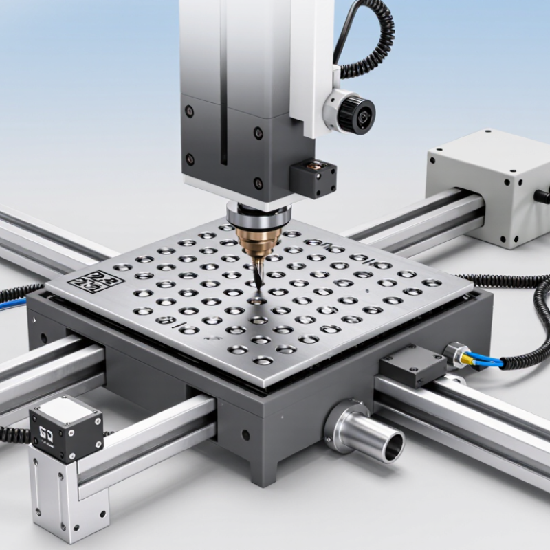
Dot peen marking creates identification directly on a metal or hard plastic surface. Unlike printing, it forms a permanent pattern through controlled impact. The marking head contains a hardened stylus, which moves toward the workpiece and strikes it repeatedly. Each impact leaves a small indentation.
The controller guides the stylus across programmed coordinates. A single dot may look insignificant, but thousands of dots can form letters, numbers, logos, or machine-readable codes. The stylus can be driven by an electromagnetic or pneumatic mechanism. Impact force, spacing, and travel speed determine the mark’s depth and appearance.
A clean mark is not automatic. Surface hardness, coating thickness, and part stability all affect the result. I have found that a rigid fixture often matters as much as the marking settings. If the component shifts, the dots stretch into uneven lines. If the force is excessive, the surface may deform around the characters. That risk is easy to underestimate.
Operators usually test several settings on a spare area before production. They check dot depth with visual inspection and verify code readability under practical lighting. Curved surfaces require careful positioning because the stylus must meet them at a consistent angle. Even then, small variations can remain. This is where process records and regular verification become valuable.
The Marking Sequence: From Artwork and Settings to a Dot-Matrix Pattern
Dot peen marking begins with artwork or text entered into the controller. The software converts each character, logo outline, or code into coordinates for a matrix of impact points. An operator then sets mark dimensions, dot spacing, pin speed, and impact force. Material matters: a hard steel part may need different settings from a soft aluminum plate.
The part is clamped firmly, and the marking head is positioned over the target area. A test mark on a sample helps reveal shallow dots, blurred edges, or uneven spacing before the production part is marked.
Then the pin taps the surface in sequence, leaving small, permanent indentations. There is a catch. A clean preview can still produce a poor mark if the part shifts or the pin is worn.
Deloitte’s 2019 Smart Factory study surveyed manufacturers. It reported that 86% saw smart-factory solutions as key competitiveness drivers over the following five years. That finding supports linking marking settings and serialized data with digital production records, but it does not measure dot peen performance itself. For reliable results, inspect the actual mark under consistent lighting, check readability, and record the settings used. A slightly imperfect test is useful: it can show where the process needs adjustment before the pattern is repeated across a batch.
Choosing Marking Depth and Speed: Match Impact Settings to Material and Traceability Needs
Dot peen settings must balance readable depth with marking time. Greater impact energy usually creates deeper indents, but thin walls may distort, and tightly spaced dots can merge. Motion speed matters too: if the impact rate stays constant, faster travel leaves wider spacing. That can weaken small characters or Data Matrix cells. Test first.
Use coupons made from the actual alloy, with the same finish and thickness as the part. Record impact energy, speed, pin spacing, and measured depth; then check readability after coating or cleaning. A profilometer can quantify depth, while a verifier checks code quality. ISO/IEC 29158:2020 describes verification for direct part marks; ISO/IEC 15415 uses a 0–4 quality grading scale. Those references help turn “looks clear” into a repeatable check. Still, a high grade does not prove a mark will survive every service condition. Set the minimum depth from real wear and traceability needs, not appearance alone. Test, then verify.
Dot Peen Marking: Choosing Depth and Speed
Example starting target depths for coupon trials by material. These are practical estimates, not universal specifications.
How to use: Begin near the suggested depth, then test on a sample of the actual material. Higher marking speed generally reduces impacts per unit length and may produce a shallower mark; adjust speed and impact setting together to meet legibility and traceability requirements without excessive deformation.
Verifying Mark Quality: ISO/IEC 29158 DPM Grading and Data Matrix ECC 200 Capacity of 2,335 Characters
Dot peen marking creates a Data Matrix by pressing a stylus into a metal surface, forming a pattern of small, permanent depressions. The code may look crisp to the eye and still scan poorly. Surface glare, curved parts, uneven dot spacing, and shallow impacts can weaken cell contrast. Small details matter.
ISO/IEC 29158:2020 provides a direct-part-mark quality grading method. It evaluates factors such as cell contrast, modulation, fixed-pattern damage, and grid distortion under specified imaging conditions. A verifier reports a grade, rather than relying on a quick phone scan.
ISO/IEC 16022:2006 defines the Data Matrix ECC 200 symbology; its largest 144 × 144 module symbol can hold up to 2,335 alphanumeric characters, or 1,556 bytes. These are theoretical capacities, not sensible targets for every part. Dense codes need finer dots and more reliable marking control.
For production checks, verify samples from different locations and orientations, then record the grade and settings. A clean, flat coupon may pass while a curved component fails. That gap deserves attention. ECC 200 error correction can recover some damaged data, but it cannot rescue every distorted mark. Recheck after changes to material, marking depth, or lighting; one stable setup does not prove every batch is stable.